UCLA plasma lab
PSPL Biased Filter Study
A lab research report on a dual-layer biased filter for secondary species emissions from electric-thruster beam targets.

Proof surface
| Claim | Public proof | Private boundary | Status |
|---|---|---|---|
| Biased-filter concept | Archival-cleaned PSPL report and extracted COMSOL/MATLAB figures. | Original lab folders and editable source files are not published. | Archival cleaned |
| Simulation workflow | Page shows electrostatic field, particle tracing, phase diagram, and SolidWorks model figures. | Only report-ready figures are public. | Public figure set |
Biased-filter concept
- Public proof
- Archival-cleaned PSPL report and extracted COMSOL/MATLAB figures.
- Private boundary
- Original lab folders and editable source files are not published.
- Status
- Archival cleaned
Simulation workflow
- Public proof
- Page shows electrostatic field, particle tracing, phase diagram, and SolidWorks model figures.
- Private boundary
- Only report-ready figures are public.
- Status
- Public figure set
Research frame
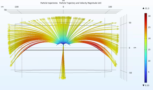
The PSPL project studied a practical measurement problem in electric-thruster ground testing. When an ion beam strikes chamber hardware or a beam target, secondary species emissions can contaminate particle-density and current measurements. The report proposed a biased electrostatic filter: a dual-layer charged grid placed near the beam target to suppress lower-energy secondary particles while letting the higher-energy incident beam pass with minimal disruption.
What was modeled
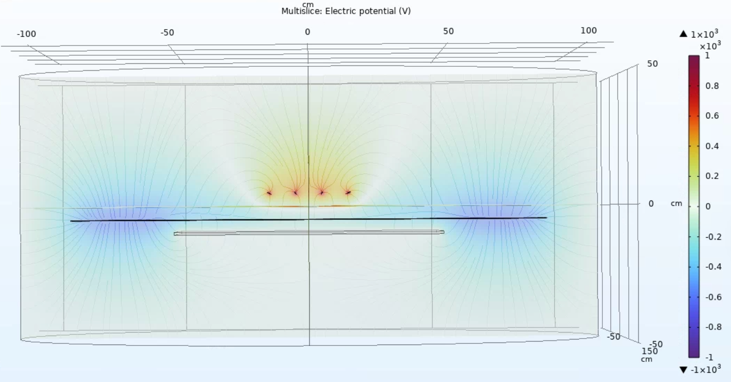
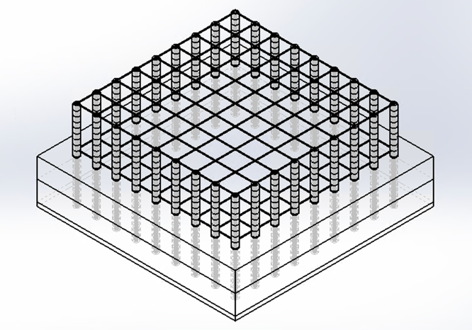
The model treated the vacuum chamber as a grounded cylindrical domain and placed charged tungsten-wire grids between the beam target and the region where secondary particles would rebound. The design variables were intentionally physical: wires per layer, layer count, parallel separation, vertical clearance, wire radius, and applied potential.
- define chamber and beam target geometry
- parameterize wire-grid design
- solve electrostatic field
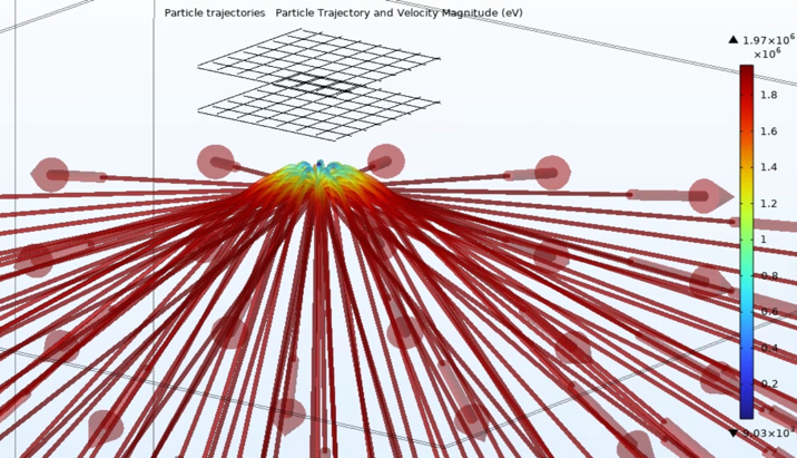
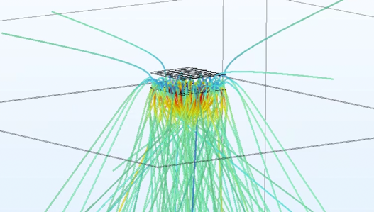
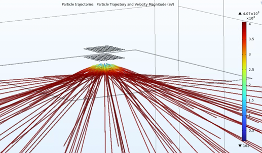
- trace secondary particle trajectories
- summarize geometry-performance tradeoffs
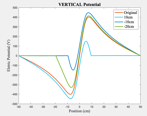
The report moved through staged simulations. Early runs validated the field shape in simple geometries. Later stages compared vertical clearance, parallel separation, voltage-sign ordering, and particle tracing behavior. The central engineering question was not whether a charged grid can create a field. It was which geometry gives useful suppression without becoming impossible to manufacture or disruptive to the test environment.
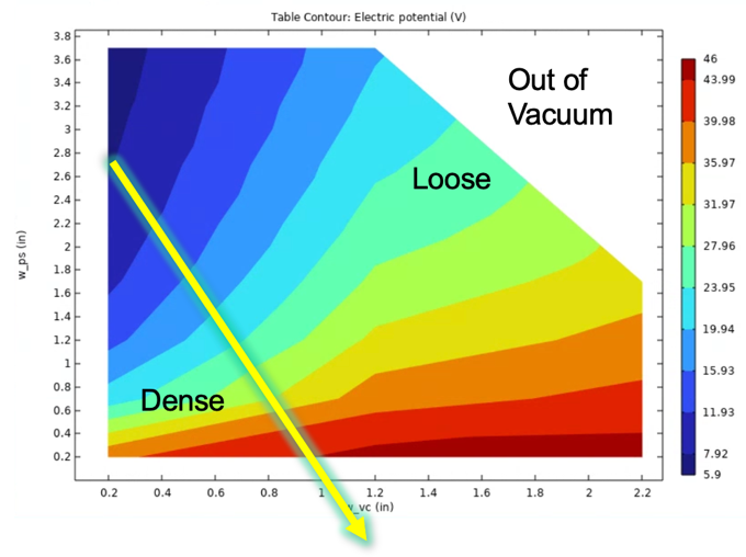
Simulation evidence
These are the figures that carry the project: trajectory traces, field visualization, a parameter-sweep phase diagram, and the manufacturable SolidWorks model. They come from the PSPL report itself rather than from a console capture.
Design comparison
| Design choice | Result | Interpretation |
|---|---|---|
| Alternating polarity | Weak central potential in several geometries. | Neighboring layers partially cancel the field where suppression is needed. |
| Separated polarity | Stronger useful potential. | Grouping same-sign layers preserves a more meaningful barrier near the target. |
| Smaller parallel separation | Higher central potential. | Denser grids strengthen the local field but raise manufacturing and obstruction costs. |
| Larger vertical clearance | Stronger potential under opposite-polarity assumptions. | Geometry matters as much as voltage magnitude. |
Why it belongs here
This is not legal AI work, but it explains a lot about the later legal-data work. The habit is the same: build the geometry, name the assumptions, run the model, inspect the output, and do not let a clean-looking result hide the measurement problem underneath.